Technical Problems
| Author(s) | J.S.S.G. de Jong | |
| Moderator | J.S.S.G. de Jong | |
| Supervisor | ||
| some notes about authorship | ||
Lead reversals


Lead switches are a common mistake when ECGs are made and can lead to wrong diagnoses. Common mistakes are:
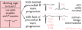
- Left-right arm reversals lead to a negative complex in lead I with a negative P wave in lead I. They are one of the most common causes of right axis deviation on the ECG!
- Arm-foot switches lead to a very small or 'far field' signal in leads II or III.
- Chest lead reversals lead to inappropriate R wave progression (increase-decrease-increase) and are often easily recognized.
Therefore any right axis or small signal in an extremity lead should be reason enough to check lead positioning. A previous ECG can be very helpful.
More specific patterns with every lead reversal:
- right and left arm electrodes:
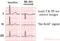
- inversion of lead I
- reversal of leads II and III
- reversal of leads aVR and aVL
- right leg and right arm:
- diminished signal in lead II
- left arm and left leg:
- reversal of leads I and II
- reversal of leads aVL and aVF
- inversion of lead III
- right arm and left leg:
- inversion of leads I, II and III
- reversal of leads aVR and aVF
It is possible to distinguish lead reversal and dextrocardia by watching the precordial leads. Dextrocardia will not show any R wave progression in leads V1-V6, whereas lead reversal will.
-
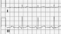
 Right and left arm lead reversal can be distinguished from the (much rarer) dextrocardia by examination of the precordial R wave progression.
 -
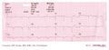
 Right arm and left leg lead reversal. Lead II now measures the signal between the left and right leg, which is remote from the heart.
 -
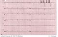
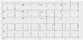
 A patient with dextrocardia (and previous inferior myocardial infarction)
 -
 Another patient with dextrocardia


Artifacts
Artifacts (disturbances) can have many causes. Common causes are:
- Movement
- Electrical interference
Filter settings
Although not a technical problem, filter settings influence the interpretation of the ECG.[1]

To reduce electrical interference ECG machine use two filters:
- A high-pass filter reduces low frequency noise. This filter reduces base line drift on the ECG.
- A low-pass filter reduces high frequency noise, such as produces by chest and extremity muscles and electrical interference from the power grid.
Depending on the purpose of the ECG these filters can be adjusted.
- In the monitor mode the high-pass filter can be set higher at 0.5-1.0 Hz and the low-pass filter on 40 Hz. This is the strongest filter setting (only a narrow frequency range is passed by the filter). This setting is especially useful for rhythm monitoring where noise can be distracting and ST segment interpretation is not very important. In this mode, pacemakerspikes are sometimes invisible while filtered out.
- In the diagnostic mode the high-pass filter is set at 0.05 Hz and the low-pass filter at 40, 100 or 150 Hz. This improves the diagnostic accuracy of the ST semgent. On the downside a base line drift occurs more easily.
-
 Movement artifacts
 -
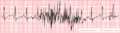
 Increasing movement artifacts in a Parkinson's patient. The patient was in sinus rhythm (which doesn't show on this short recording)!
 -
 Baseline drift. The amplifier in the ECG machine has to re-find the 'mean'. This often occurs right after lead connection and after electric cardioversion.
 -
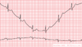
 Cardioversion from atrial fibrillation to sinus rhythm, with clear baseline drift.
 -
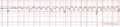
 Electrical interference from a nearby electrical appliance. A typical example is a 100 Hz background distortion from fluorescent lights. Not to be confused with atrial fibrillation.
 -
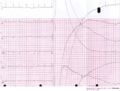
 Another example of an artifact caused by an electrical appliance. The patients rhythm is regular. This strip shows 10 QRS complexes.
 -
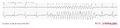 An artifact that was originally diagnosed as a VT


