QRS axis: Difference between revisions
mNo edit summary |
|||
| Line 11: | Line 11: | ||
}} | }} | ||
[[Image:hartas2.jpg|thumb|The heartaxis indicates the average direction of the depolarization wave. A normal heartaxis, the picture shows an example, is between -30 and +90 degrees. In this example, the heartaxis is +45 degrees.]] | [[Image:hartas2.jpg|thumb|The heartaxis indicates the average direction of the depolarization wave. A normal heartaxis, the picture shows an example, is between -30 and +90 degrees. In this example, the heartaxis is +45 degrees.]] | ||
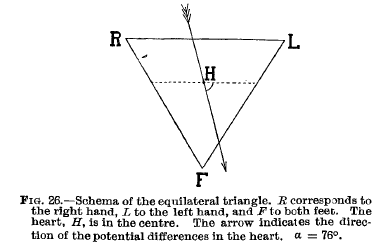
[[Image:einthhartas.png|thumb|Heartaxis from the original publication of Einthoven. Reprinted from The Lancet, March 30 1912, Einthoven W., | [[Image:einthhartas.png|thumb|Heartaxis from the original publication of Einthoven. Reprinted from The Lancet, March 30 1912, Einthoven W., | ||
| Line 20: | Line 19: | ||
For a lot of people, this is a difficult concept. The theoretic part seems difficult but by doing it a lot, it will become clear. | For a lot of people, this is a difficult concept. The theoretic part seems difficult but by doing it a lot, it will become clear. | ||
{{clr}} | {{clr}} | ||
{{clr}} | |||
==The heartaxis simulator== | |||
{| class="wikitable" align="right" | |||
|<flashow>http://nl.ecgpedia.org/images/c/cc/Heartaxis.swf|height=350px|width=700px|</flashow> | |||
|- | |||
| The heartaxis simulator, made by Bart Duineveld. Turn the heart-axis arrow and see how the QRS complexes change. [[media:Heartaxis.swf|Link to the original filel]] for use in powerpoint presentations or full screen viewing. | |||
|} | |||
{{clr}} | |||
==How do you determine the electrical heartaxis== | ==How do you determine the electrical heartaxis== | ||
[[Image:hart_axis.png|thumb]] | [[Image:hart_axis.png|thumb]] | ||
Revision as of 11:40, 19 December 2008
| «Step 3: Conduction (PQ, QRS, QT, QTc) | Step 5: P wave morphology» |
| Author(s) | I.A.C. van der Bilt, MD | |
| Moderator | T.T. Keller | |
| Supervisor | ||
| some notes about authorship | ||


The electrical heartaxis is an average of all depolarizations in the heart. The depolarization wave begins in the right atrium and proceeds to the left and right ventricle. Because the left ventricle wall is thicker than the right wall, the arrow indicating the direction of the depolarization wave is directed to the left.
For a lot of people, this is a difficult concept. The theoretic part seems difficult but by doing it a lot, it will become clear.
The heartaxis simulator
| height=350px|width=700px|</flashow> |
| The heartaxis simulator, made by Bart Duineveld. Turn the heart-axis arrow and see how the QRS complexes change. Link to the original filel for use in powerpoint presentations or full screen viewing. |
How do you determine the electrical heartaxis


When you average all electrical signals from the heart, you can indicate the direction of the average electrical depolarization with an arrow (vector). This is the heartaxis. Especially a change of the heartaxis or an extreme deviation can be an indication for pathology.
For example:
- Biggest QRS deflection in lead I: the electrical activity is directed to the left (of the patient)
- Biggest QRS deflection in lead AVF: the electrical activity is directed down.
This indicates a normal heartaxis. Usually, these two leads are enough to diagnose a normal heartaxis!
The biggest vector in the heart is from the AV-node in the direction of the ventricular depolarization. Under normal circumstances, this is directed left and down.(towards leads I and AVF). The position of the QRS vector is given in degrees. See the figure, the middle of the figure is the AV-node. A horizontal line towards the left arm is defined as 0 degrees.
A normal heartaxis is between -30 and +90 degrees.
Rule: biggest QRS deflection in I and II is an intermediate = normal heartaxis. So positive deflections in I and II indicates a normal heartaxis.
Interpretation
The interpretation of the electrical heartaxis has a few rules of thumb:
- First, when a positive depolarization wave moves towards a positive electrode, a positive, upwards deflection is registered on the ECG.
- Second, there are 4 quadrants where the QRS-vector can point to:
- left upper quadrant --> left axis deviation (between -30º and -90º)
- left lower quadrant --> normal (between -30º and 90º)
- right below and right --> right axis deviation (between 90º and -150º)
- right upper quadrant --> extreme axis (between -90º and -150º)
Example:
The QRS in lead I, will have a negative deflection in a right axis deviation. The vector is not directed towards the electrode. However, lead AVF will be positive, the vector is directed towards the electrode.
Heart-axis Simulator
To understand how the ECG changes in axis deviations, this excellent axis-simulator may be helpful: http://www.blaufuss.org/ECGviewer/indexFrame2.html
Iso-electrical
Note: When the depolarization is perpendicular on the lead, this is called iso-electrical. The QRS is neither positive nor negative.
Undetermined axis
When all extremity leads are biphasic, the axis is directed to the front or back, in a transverse plane. The axis is than undetermined.
Abnormal heartaxis


The direction of the vector can changes under different circumstances:
- When the heart itself is rotated (right ventricular overload), obviously the axis turns with it.
- In case of ventricular hypertrophy, the axis will deviate by the bigger electrical activity and the vector will turn towards the hypertrophied tissue.
- Infarcted tissue is electrically dead. No electrical activity is registered and the QRS vector turns away from the infarcted tissue
- In conduction problems, the axis deviates too. When the right ventricle depolarizes later than the left ventricle, the axis will turn to the right (RBBB). This is because the right ventricle will begin the contraction later and therefore will also finish later. In a normal situation the vector is influenced by the left ventricle but now only by the right ventricle.
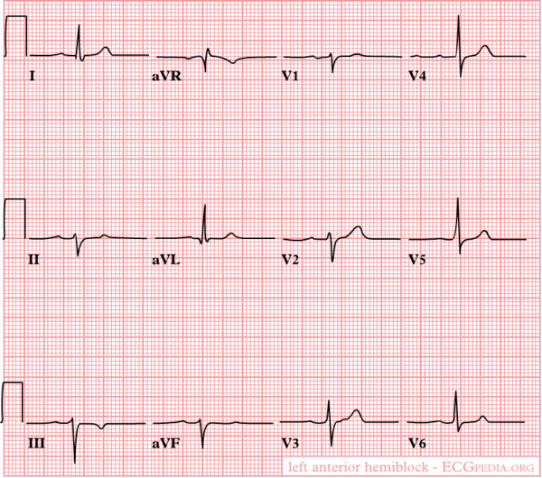
Examples of a left heartaxis


- left anterior fascicular block
- Inferior myocardial infarction
- Left ventricular hypertrophy
- Pacemaker rhythm
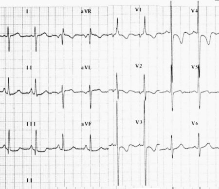
Examples of a right heartaxis

- Right ventricular hypertrophy
- Right ventricular load, for example Pulmonary Embolism or Cor Pulmonale (as in COPD)
- Atriumseptumdefect, ventricleseptumdefect
Microvoltages


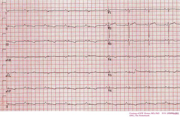
- microvoltages
- The QRS amplitute (i.e. the sum of the postive and negative parts) in the limb leads does not exceed 0.5 mV (5 mm) OR is no more than 1.0 mV (1 cm) in the chest leads.
Possibe causes of microvoltages:
- Cardiomyopathy, especially infiltrative cardiomyopathy, such as in amyloidosis
- Increased resistance between the heart and the electrodes: pneumothorax, obesesity, pericardial fluid / tamponade, pleural effusion
- Myocarditis / pericarditis
- Heart tranplantation, especially during acute or chronic rejection
- Wrong settings on the ECG apparatus (sensitivity should be at 10 mm/mV)